
_JPG.jpg)
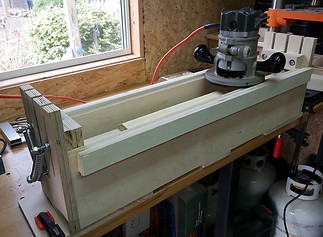
height of the router, this design would allow me to adjust the point at which the cam was stopped. In this way I could use this prototype to determine the ideal specification for the final jig. The threaded rods of these blocks of wood also served to secure the end of the springs that were otherwise attached to the axles and that pulled the axles (and thereby, the cams) up into the wood blocks.
The lower image shows the blocks, one of the cams and one of the "necks" used to test the jig.
The blocks each featured an aluminum cylinder (actually pieces cut to size with a bandsaw from a sacrificial broom handle) epoxied into a cavity drilled with a forstner bit. I assumed the cylinders would be slippery enough to allow the necessary movement of the cams. The image suggests how a cam is pulled up towards a block and how it runs on the surface of the cylinder.
The cams were made to be replaceable. This was done for two reasons. Firstly, I was unsure of the exact size and shape required for each cam to define the desired profiles, so I would need to modify or replace the cams following experimentation and observation. Secondly, even once the exact sizes and shapes for a given neck were known, I would want to ultimately have a working jig with interchangeable cams to allow for different guitar models and different neck profile preferences - custom widths at the nut, for example.
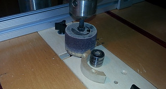
Creating the shape of the cams presented some challenges. I won't detail how this was done in this article, because in order to solve the problem I replaced my purchased drill press table with a shop-made table with some innovative features, and this table, as well as how it was used to create the cams, will be featured in an article in the next issue of the newsletter. The table, which has interchangeable components to tackle different tasks, is shown in the lowest image, where it is being used to create templates that were used with a flush-trim router bit to create the jig's cams.
Other design features of this jig are not particularly remarkable. For example, the router base simply slid on the top of the plywood sides of the box and were prevented from sideways movement by an outer strip of plywood glued to each side of the box.
So... how did it work?
Well... it was OK. Not perfect by any means, but the results were at least good enough to suggest that I was on the right track and
SOLG Newsletter - Issue 2 - September 2020
Page 15